Fruity Solar Cell: The Effects of Dye Bath, Light Intensity, and Surface Area of Electrodes on the Efficiency of Dye Sensitised Solar Cells - Emaan Faisal
- thevisionairemagaz
- Oct 30, 2024
- 14 min read

Abstract
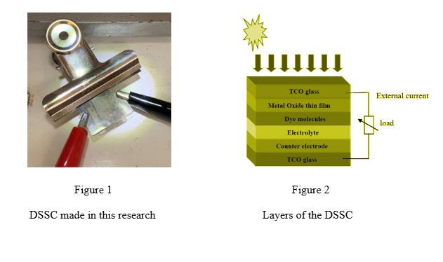
A Grätzel cell, also known as a Dye-Sensitized Solar Cell (DSSC), is an innovative solar technology that harnesses light energy through a photoelectrochemical system. Constructing this cell involves two primary components: the working electrode and the counter electrode. The working electrode is prepared using a fluorine-doped tin oxide (FTO) glass slide coated with a layer of titanium dioxide (TiO2), which is sensitized with a dye containing an organic molecule known as anthocyanin. The counter electrode, also an FTO glass slide, is coated with graphite, and both electrodes have an electrolyte sandwiched between them. This study examined the effects of changing dye baths, light intensity, and surface area of electrodes on the efficiency of DSSCs. The dye bath was varied by using blueberries and strawberries, light intensity was varied by changing the input light intensity (therefore input power), and surface area was changed by changing the width of the TiO2 semiconductor layer on the working electrode. In each case, only the experimental variable was changed, and efforts were made to keep all other potentially extraneous variables constant. The values of voltage and current generated by each DSSC were measured using a multimeter and power output was calculated. These values were input into the formula for calculating the efficiency of a solar cell. We hypothesized the effect of each variable before the experiment through our research and all our hypotheses were met: increased anthocyanin content, increased surface area, and light intensity all increase the efficiency of a DSSC. This research topic is of considerable interest to those in the fields of renewable energy, material science, and environmental sustainability. By exploring the potential of DSSCs, scientists and engineers can uncover new ways to harness solar power more efficiently, leading to broader applications in sustainable energy solutions.
The Effects of Dye Bath, Light Intensity, and Surface Area of Electrodes
on the Efficiency of Dye Sensitised Solar Cells
Dye-sensitized solar cells are thin-film solar cells which have been the focus of substantial research as they are an economic alternative to the p-n junction photovoltaic cells (1). According to Sharma, K., Sharma, V., & Sharma, S. S., the initial efforts to create such solar cells were attempted first in 1972 with the invention of chlorophyll-sensitized zinc oxide electrodes. Due to the lower efficiency of ZnO-single crystals caused by less incident light being absorbed by the monolayer, titanium dioxide electrodes were invented in 1991, and cells made from them - Grätzel cells made by Brian O’Regan and Michael Grätzel - initially had an efficiency of 7%. (2) The TiO2 film in this device was coated with a charge transfer dye. By 1998, this cell had reached an efficiency of 10% (1).
This topic sparked our interest as we are all physics students who have grown up studying about energy crises, especially in our home country Pakistan. We have always been familiar with strategies to reduce energy consumption and try to limit our contribution to global warming. A DSSC was the most accessible cell we could assemble and investigate. We wanted to investigate relevant parameters that directly affect the efficiency of such a cell, and came up with hypotheses based on our research, the results of which will be discussed later.
The cell we used in this experiment (3) is made up of 2 FTO-coated glass slides acting as electrodes pressed against each other. On the conducting side of each, the electrode layer is formed. The working electrode is covered with a layer of dry titania paste (made of titanium dioxide nanoparticles mixed with dilute nitric acid), followed by a layer of natural fruit dye absorbed into the TiO2 film. The counter electrode simply has a layer of graphite which we provided using HB pencils. Before placing the counter electrode on top of the working electrode, an electrolyte layer typically made of iodide and triiodide is put on the working electrode. Both electrodes are joined, leaving enough space on each electrode so that both of the multimeter probes can be attached by alligator clips.
The question that comes to mind is: what is the purpose of each of these components and why is each necessary? Although FTO slides are a necessary component, we tried this experiment with simple glass slides while we were in the process of acquiring the FTO slides and, as expected, there were no readings on the multimeter. FTO slides are needed to provide a conducting layer so the cell is complete. The FTO layer is fluorine-doped tin oxide, which is transparent and conducts electricity. TiO2 is a semiconductor containing nitric acid used in the cell to absorb light, without which the cell will not be able to conduct any electricity. Since TiO2 is white, it reflects light and so is unsuitable for use in its standard form. The increased porosity of this nanoparticle helps increase efficiency. A molecular dye, such as that found in raspberries, can be used to ‘sensitize’ the semiconductor to visible light. The dye molecules belong to a group called anthocyanin molecules. They can be alcohol groups or ester groups, which help the dye bind to the semiconductor. Iodine ions act as the electrolyte solution, which completes the circuit and conducts/allows the flow of electricity. Graphite is used as the counter electrode as it conducts electricity, completing the electric circuit required for the solar cell to work. The working and counter electrodes in the solar cell act as the anode and cathode.
The working principle of the DSSC is as follows (3): the process starts at the working electrode when the sensitizing dye (i.e. the blueberry juice bound to the TiO2 layer) absorbs light. The energy from the light (through photons) allows the dye to excite an electron to a higher energy level.
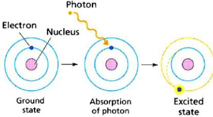
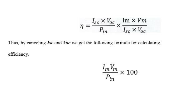
Figure 3 Electron excitation (4)
An electron can become excited if it is given extra energy (absorbs a photon/packet of energy from the visible light spectrum, collides with a nearby atom, etc.). Photons will excite the dye molecules' electrons (ground state (S) to the excited state (S∗) shown by S + hv → S*), and the electrons will jump from the dye molecule to the “conduction band” of the titanium dioxide, oxidizing it (shown by S* → S⁺ + e⁻ ) (1).
From the excited state, the electron is injected into the TiO2 semiconductor. The electron travels around the circuit to the counter electrode, powering an external load. The sensitizing dye is reduced by the reversible redox couple provided by the iodine/iodate(I- / IO–3) electrolyte (shown byS⁺ + e⁻ → S and I₃⁻ + 2 e⁻ → 3 I⁻ ). The carbon is a catalyst for this reduction (6). We used iodate (IO–3) instead of triiodide (I–3) as they both can be used as electrolytes (5), and also due to the unavailability of triiodide at our lab. The regeneration of this reduced sensitizing dye sustains the conversion of light energy.
Fig 4 is a diagram showing the path taken by an electron when the process starts.

Where Isc is the short circuit current (current flowing through circuit in absence of voltage), Voc is the open circuit voltage (voltage observed when no current flows through the circuit), Im is the maximum current flowing through the circuit, Vm is the maximum voltage flowing through the circuit, Pin is the input power, and FF is the fill factor (a metric used to evaluate a cell’s quality). By putting all the components into the main efficiency equation, we get the following equation,
Moving on, the variables we investigated, as mentioned in the paper title, are dye bath, light intensity and surface area of electrodes. Other suitable electrolyte compounds could also have been investigated but were unavailable to us. We investigated light intensity to replicate how sunlight has different intensities throughout the day, dye bath to see whether a change in anthocyanin content has an effect on the efficiency (we only experimented with dyes containing anthocyanin, rather than dyes made of different compounds such as ruthenium), and surface area of electrodes to understand whether it’s better for a solar panel to be made of cells of smaller or larger size. We then made hypotheses based on our research.
Firstly, we hypothesized that increasing anthocyanin content would increase efficiency. The darker the anthocyanin color, the higher the energy conversion efficiency because the darker colour will enhance light absorption (8). In a research conducted to understand the effect of different dyes on the efficiency of a DSSC, Bohnenkamp et al found that ‘the best results were gained by dyes containing anthocyanins’, which were present in both dyes used in our experiment (9). According to Skrovankova et al, “The anthocyanin content of strawberries, compared to other common berries, is much lower than in blueberries” (10), which further supports our hypothesis.
We hypothesized that an increase in light intensity would increase the efficiency of the cell (11). As light intensity increases, the power input also increases. As intensity ∝ power and power = energy/time increased intensity of input power means the energy supplied to the dye is greater. More electrons would be excited, resulting in greater photoexcitation. Due to improved excitation, the flow of electrons in the circuit will also be greater, allowing more short circuit current to be generated. As current ∝ voltage, increased current corresponds to increased open circuit voltage generation. So according to the initial formula to calculate efficiency, the overall efficiency of the system increases, provided the fill factor remains constant (does not decrease).
Lastly, we hypothesized that an increase in the surface area of electrodes would increase the cell’s efficiency. An increased surface area means there is more of the semiconductor on the electrode (the area of the semiconductor layer is the surface area of the electrode). To enable full coverage, more dye is used as well. With this combination, more dye binds with the semiconductor. An increase in dye results in greater absorption of energy and more photoexcitation. More electrons are injected into the conduction band of the adjacent titanium dioxide semiconductor, resulting in greater photocurrent generation (12).
Method
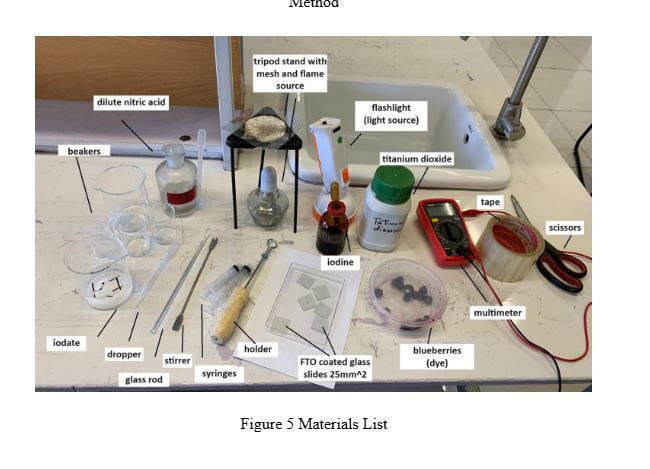
Figure 5 shows the materials we used, which are as follows: beakers (to make the semiconductor paste and electrolyte solution), iodate, dropper, glass rod, stirrer, syringes (to add the dye), holder, FTO-coated glass slides (25 mm2), iodine, blueberries, strawberries, multimeter, tape, scissors, titanium dioxide, flashlight, tripod stand with mesh and flame source, dilute nitric acid.
It’s important to note that the mesh was cleaned after this picture was taken (before experimentation). This experiment was conducted indoors using the flashlight as the light source. A flashlight was used specifically to monitor the power input to the cell. The one we used is the DP9035B. The front head has power of 1.5W on ‘mode 1’ and 3W on ‘mode 2’. All the experiments were conducted in the same setting, so any incident light apart from the torchlight had the same effect on the experiments, thus we assumed there is no net effect of the surrounding light on the output power from the cell.
Setup Picture

Figure 6 shows the torch setup. A retort stand and meter rule were used to maintain the torch height, which was constant at 50.0cm throughout the experiments. Attaching both alligator clips from the probes of the multimeter shows a reading on the multimeter. Figure 7 shows the DSSC placed on the surface, getting direct torchlight.
Before the experiment, the titania paste was made. Titanium dioxide was mixed with dilute nitric acid to a consistency similar to paint. The electrolyte solution was also made beforehand by combining 1.25g iodine and 2.5g iodate in 25 ml.
Constructing the DSSC
The first step would always be to check the conducting side of the glass slide using the multimeter probes. Two edges of a slide were taped to a tile with the conducting side facing upwards. The stirring rod was used to place some of the titania paste on one uncovered edge of the slide. The rod’s length was used to thin the paste out smoothly. This method is for an electrode with surface area of 25 mm by 17 mm. It was left to dry for 5 minutes, then placed on the mesh (atop the flame source) using forceps. The slide was left to anneal for 10 minutes. Meanwhile, the dye was prepared by mashing blueberries and extracting pure juice into a syringe. Once the TiO2 was annealed, 1.5ml of the dye was applied to it and left to bind to the semiconductor for 10 minutes. The counter electrode was then prepared.
For all experiments, the same HB pencil was used and a criss-cross pattern was rubbed onto the conducting side of the counter electrode. The excess dye on the working electrode was rinsed with distilled water and the electrode was lightly pat-dried. A clip was used to attach the two electrodes in a sandwich formation. Next, 1.5 ml of the electrolyte solution was poured into the cell from the side.
Finally, the crocodile clips from the multimeter were attached to the protruding end of each electrode, the cell was placed directly under the torch setup and the reading on the multimeter was observed. For each cell, the current was measured in microamps (A) and voltage was measured in millivolts (mV) to calculate efficiency.
In all experiments, protective eyewear was worn and the flame source was used only for annealing, otherwise, it was blown out.
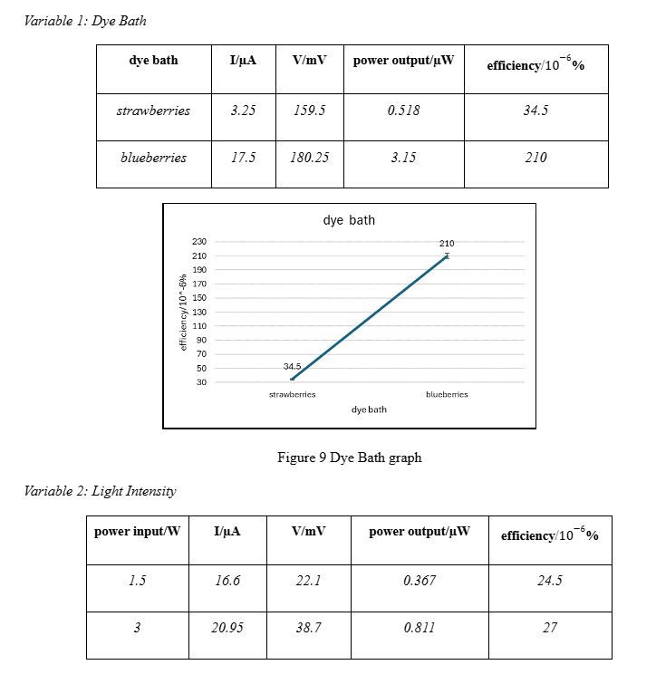
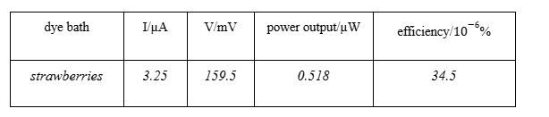
Variable 1: Dye Bath
As mentioned before, the dyes were varied on the basis of differences in anthocyanin content. To do this, we used blueberries and strawberries. Pure juice was extracted from both fruits and placed onto the respective working electrodes, as can be seen in Figure 8. The cells were made as described above. The surface area of both working electrodes (25 mm by 17 mm), the incident light intensity from the torch (1.5W), and aspects such as torch height from surface (already described above) were kept constant. Figure 8 Variable 1
Variable 2: Light Intensity
In this case, one cell made from blueberry dye was used. The surface area (25 mm by 17 mm), and height of the torch from the surface were also kept constant. Here, the light intensity was varied by using two “modes” of the torch, giving Pin as 1.5W and 3W.
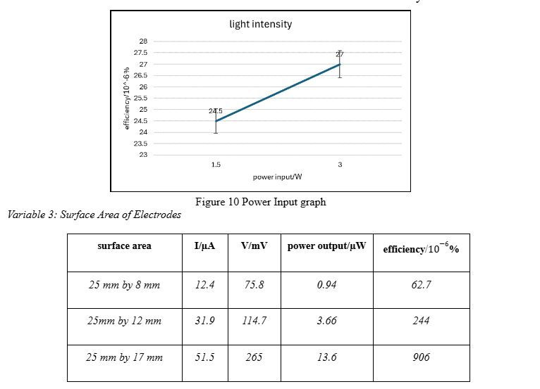
Variable 3: Surface Area of Electrodes
To investigate the effect of changing the surface area of electrodes, we made 3 working electrodes simultaneously. All of them used blueberry dye, the torch height from the surface was the same, and the incident light intensity was 1.5W. The different surface areas used were: 25 mm by 17 mm, 25mm by 12 mm, and 25 mm by 8 mm. They needed electrolyte solution and dye bath corresponding to the surface area, so the overall change observed is due to the change in surface area. If they had different surface areas but same volume of dye and electrolyte, the comparison would not be fair. Therefore, the volumes of dye and electrolyte added to each cell were 1.5ml, 1.0ml and 0.5ml, respectively.
Results
It is important to note that we did not add any external load to our cells. We measured Im and Vm and input those into the efficiency formula described above. The results for each investigation are as follows:
Discussion
As described in the introduction, our experimental and calculated data met our hypotheses for each variable. The darker the anthocyanin colour, the higher the energy conversion efficiency because the darker colour will enhance light absorption. Blueberries are much darker than strawberries, which explains the increasing trend. However, a spike of over 100 units on the y-axis suggests there may be another reason. It is possible that the dye from strawberries was not able to bind to the semiconductor as well as the dye from the blueberries. From our observation during the experiment, the blueberry dye did appear more prominently. Moving onto the light intensity, the increase in efficiency is evidenced by doubling the light intensity. Increased intensity of input power means the energy supplied to the dye is greater. Due to improved excitation, the flow of electrons in the circuit will also be greater, allowing more current to be generated. It’s important to note that there isn’t a spike as steep as the one from variable 1 in this case. This can be explained by the small difference in the light intensity we used, which was 1.5W. It’s possible that a larger input power would give a value as huge as, or comparative to, the value for blueberry dye. An increase in surface area of electrodes corresponds with an increase in efficiency due to more TiO2 nanoparticles being present, requiring more dye for a functioning cell to be made, resulting in greater absorption of energy. More electrons are injected into the conduction band of the adjacent titanium dioxide semiconductor, resulting in greater photocurrent generation. An outlier to consider here is the efficiency value for the area of 25 mm by 17 mm. In the first two variables, electrodes had the same area as this but their efficiencies were at least 3 times smaller. Comparing blueberry dye from variable 1 with the third data value from variable 3, the efficiencies are 210 10-6% and 906 10-6%, respectively. They should be in the same range, if not identical. This indicates that this value is an outlier. Possible explanations for this include better dye absorption of the dye on the semiconductor, differences in the “age” of the DSSC used, etc.
Overall, our experiment was successful in terms of finding the answers to our questions. We were unable to attach a singular cell to an external component, which understandably did not work due to the low power output from a single cell. With a series of cells connected, however, this could be a possibility. We could also try this experiment under natural light from the Sun and compare our results. We hope this research is useful to us as well as other amateur researchers in the quest to find answers to scientific questions.
Appendix
The following formula (31) shows the error calculation method in a multimeter = ±{(accuracy error rate <%> × reading) + range error }. The multimeter we used is the UT33B+ (32).
Our multimeter’s percentage error:
Voltage (V/mV): ±(0.5% of reading + 2 digits)
Current (I/µA): ±(1.0% of reading + 2 digits)
Following this we calculated the absolute errors for our readings. For example:
Percentage Error: in current
Percentage Error = 1.0%×3.25 μA = 0.0325 μA
Range Error (Digits Error):
The resolution is 0.01 µA,
2 digits: 2×0.01 μA=0.02 μA
Total Error: Total Error=±(0.0325 μA+0.02 μA)=±0.0525 μA
Percentage Error: in voltage
Percentage Error=0.5%×159.5 mV = 0.7975
Range Error (Digits Error):
Assuming the resolution is 0.1 mV,
2 digits: 2×0.1 mV=0.2 mV
Total Error: Total Error=±(0.7975 mV+0.2 mV)=±0.9975 mV
Total error in power output =0.0525 + 0.9975 = ±1.05
Now for error in efficiency, we have to consider the error in Power Input and Power Output. The total error for power output is now calculated. For power input, we are assuming there is no error as we are using a standard torch which has set values for power provided by the manufacturer. This means that the total error in power output is the absolute error in the efficiency calculated. Following this method we have calculated percentage errors and made the error bars for each reading in our sample.
Literature Cited
Sharma, K., Sharma, V., & Sharma, S. S. (2018). Dye-Sensitized Solar Cells: Fundamentals and Current Status. Nanoscale research letters, 13(1), 381. https://doi.org/10.1186/s11671-018-2760-6
O'Regan, B., Grätzel, M. A low-cost, high-efficiency solar cell based on dye-sensitized colloidal TiO2 films. Nature 353, 737–740 (1991). https://doi.org/10.1038/353737a0
Royal Society of Chemistry Education, in association with The Solar Spark at the University of Edinburgh, Make a Gratzel Cell, https://edu.rsc.org/resources/make-a-grtaand776zelcell/1290.article
Streeter, Jackson & De Taboada, Luis & Oron, Uri. (2004). Mechanisms of action of light therapy on acute myocardial infarction and stroke. Mitochondrion. 569-76. 10.1016/j.mito.2004.07.037
Manoj Kumar, Potassium Iodate Formula, Structure, Properties, Uses, Physics Wallah, https://www.pw.live/exams/school/potassium-iodate-formula/#:~:text=Potassium%20Iodate%20Formula%20is%20KIO,various%20cell%20and%20nerve%20functions.
Neal Abrams, Constructing a Dye-Sensitized Solar Cell, YouTube, (09.10.2009), https://youtu.be/17SsOKEN5dE
Chetan Kumbhar, How Is Solar Panel Efficiency Measured?, EE Power (March 21 2023), https://eepower.com/technical-articles/how-is-solar-panel-efficiency-measured/#
Viqry Pramananda et al, Anthocyanin as a natural dye in DSSC fabrication: A review, (2021) IOP Conf. Ser.: Mater. Sci. Eng. 1122 012104
Bastian Bohnenkamp, Jan-Hendrik Linnemann, Irén Juhász Junger, Eva Schwenzfeier-Hellkamp, Andrea Ehrmann, Influence of dyes and dying process parameters on the electrical properties of dye-sensitized solar cells, Optik, Volume 168, 2018, Pages 282-286, (https://www.sciencedirect.com/science/article/pii/S0030402618305965)
Skrovankova, S., Sumczynski, D., Mlcek, J., Jurikova, T., & Sochor, J. (2015). Bioactive Compounds and Antioxidant Activity in Different Types of Berries. International journal of molecular sciences, 16(10), 24673–24706. https://doi.org/10.3390/ijms161024673
Ji Hoon Kim, Kook Joo Moon, Jong Man Kim, Dongyun Lee, Soo Hyung Kim, Effects of various light-intensity and temperature environments on the photovoltaic performance of dye-sensitized solar cells, Solar Energy, Volume 113, 2015, Pages 251-257, https://doi.org/10.1016/j.solener.2015.01.012.
Science Direct, Dye-synthesized solar cell, https://www.sciencedirect.com/topics/materials-science/dye-sensitized-solar-cell#:~:text=In%20a%20 dye%Sensitized%20 solar,spite%20of%20the%20simple%20process
“Dye-Sensitized Solar Cell.” Wikipedia, 25 Dec. 2020, en.wikipedia.org/wiki/Dye-sensitized_solar_cell
“Photosensitizer.” Wikipedia, 3 July 2021, en.wikipedia.org/wiki/Photosensitizer
Wikipedia Contributors. “Solar Cell.” Wikipedia, Wikimedia Foundation, 10 Mar. 2019, en.wikipedia.org/wiki/Solar_cell
“09 Juicy Solar Cell.” Www.gypt.org, www.gypt.org/aufgaben/09-juicy-solar-cell.html Accessed 12 July 2024.
“Solar Cell Efficiency Formula.” Ossila, www.ossila.com/pages/solar-cell-efficiency-formula
“Dye-Sensitized Solar Cell - an Overview | ScienceDirect Topics.” Www.sciencedirect.com, www.sciencedirect.com/topics/materials-science/dye-sensitized-solar-cell#:~:text=Typically%2C%20DSSCs%20consist%20of%20four
“Nanotechnology for Solar-To-Electricity Conversion Technology | Frontiers Research Topic.” www.frontiersin.org/research-topics/57513/nanotechnology-for-solar-to-electricity-conversion-technology#:~:text=Nanotechnology%20can%20help%20in%20this
Khan, Maham, et al. “Improving the Efficiency of Dye-Sensitized Solar Cells Based on Rare-Earth Metal Modified Bismuth Ferrites.” Scientific Reports, vol. 13, no. 1, 22 Feb. 2023, https://doi.org/10.1038/s41598-023-30000-8
Liu, I-Ping, et al. “High-Performance Printable Electrolytes for Dye-Sensitized Solar Cells.” Journal of Materials Chemistry A, vol. 5, no. 19, 2017, pp. 9190–9197, https://doi.org/10.1039/c7ta01341h
Wu, Jihuai, et al. “Counter Electrodes in Dye-Sensitized Solar Cells.” Chemical Society Reviews, vol. 46, no. 19, 2017, pp. 5975–6023, https://doi.org/10.1039/c6cs00752j
Ghasemzadeh, Farzaneh, and Mostafa Esmaeili Shayan. Nanotechnology in the Service of Solar Energy Systems, IntechOpen, 2 Dec. 2020, www.intechopen.com/chapters/73145
“Definition of Dye-Sensitized Solar Cells (DSSCs) - Gartner Information Technology Glossary.” Gartner, www.gartner.com/en/information-technology/glossary/dye-sensitized-solar-cells-dssc#:~:text=Dye%2d Sensitized%20 solar%20 cells%20(DSSCs)%20use%20an%20 organic%20dye
Zhang, Shihan, et al. “Increased Power Conversion Efficiency of Dye-Sensitized Solar Cells with Counter Electrodes Based on Carbon Materials.” RSC Advances, vol. 9, no. 38, 2019, pp. 22092–22100, https://doi.org/10.1039/C9RA03344K Accessed 6 May 2021.
Smestad, Greg P., and Michael Gratzel. “Demonstrating Electron Transfer and Nanotechnology: A Natural Dye-Sensitized Nanocrystalline Energy Converter.” Journal of Chemical Education, vol. 75, no. 6, June 1998, p. 752, https://doi.org/10.1021/ed075p752
Grätzel, Michael. “Solar Energy Conversion by Dye-Sensitized Photovoltaic Cells.” Inorganic Chemistry, vol. 44, no. 20, Oct. 2005, pp. 6841–6851, https://doi.org/10.1021/ic0508371
U.S. Energy Information Administration. “Photovoltaics and Electricity - U.S. Energy Information Administration (EIA).” Eia.gov, U.S. Energy Information Administration, 26 May 2023, www.eia.gov/energyexplained/solar/photovoltaics-and-electricity.php
Mohanty, Paramita and Akshay Tyagi, Introduction to Solar Photovoltaic Technology, Elsevier, 2015, www.sciencedirect.com/topics/chemistry/dye-sensitized-solar-cell
Hagfeldt, Anders, et al., “Dye-Sensitized Solar Cells.” Chemical Reviews, vol. 110, no. 11, 10 Nov. 2010, pp. 6595–6663, https://doi.org/10.1021/cr900356p.
FAQ: Tell me how to calculate the error of the digital multimeter, Sanwa Electric Instrument Co., Ltd., https://overseas.sanwa-meter.co.jp/support/faq/faq74.html#:~:text=%22The%20following%20formula%20shows%20the%20error%20calculation%20method.&text=When%20the%20true%20value%202.000,range%20error%20is%200.002V%E3%80%82
UNI-T UT33B+ Palm Size Digital Multimeter, Electrobes, https://electrobes.com/product/uni-t-ut33b-palm-size-digital-multimeter/#tab-description


Comments